
Research
Technical Paper Articles and Patents were consulted in the design of this rocket. Below are our research findings organized by subject.
Propellant Specification
Patent: Rocket Motor and Method
The main focus of this patent was the development of a variable thrust solid rocket motor. The major advantage of solid fuel rocket motors is their simplicity compared to liquid fuel rocket motors. Where liquid fuel requires precision fuel pumps, and storage tanks for toxic fuels, and cryogenic oxidizers, solid rocket fuel contains both the fuel and oxidizer only need an empty space to fill be contained inside the rocket [1]. This makes the rocket much more simple and reliable than a liquid fuel rocket, but it also does not have the ability to vary the thrust of the rocket by varying the rate at which fuel is combusted. Burn times are predetermined by the fuel mixture, and once the fuel is ignited, it will burn until gone without a way to stop it [1]. This is the type of engine that we will be working to develop in this project. For our small scale, thrust variation is not an issue, and changing to a motor with a different fuel mixture is simple. However, for large scale rockets, specifically in military and space applications, the rocket is often trying to hit a specific target. Without variable thrust, this can only be done through changing the launch angle of the vehicle, and control surfaces [1]. The author of this patent suggests solving this problem by designing a solid rocket motor with variable thrust. This would be achieved by building the solid rocket motors in concentric layers, but in between each layer of fuel, there would be a layer of only fuel. Due to the lack oxygen, the layer of pure fuel would fail to ignite. At this point, oxygen from a separate system could be introduced into the combustion chamber if the burn needs to continue [1]. While our rocket motor will not require this level of complexity, this patent’s system could be used with the rocket fuel that will be mixed for our design project.
Article: Solid Propellants: AP/HTBP Composite Propellants
The main focus of this article was to discuss the purpose of each of the components required when making solid rocket motors. It also discussed different chemicals that can be used for each of these components, and how they interact with each other. As a large portion of the design project is developing rocket motor mixtures, this initial background information will be invaluable. The first component in the solid rocket fuel in the oxidizer. This is the portion of the fuel that’s reaction during the ignition, and continuous burning of the fuel that gives off oxygen, which allows for the fuel to continue to burn, even in environments where ambient oxygen cannot reach the fuel [2]. The next component discussed in the paper was that of the fuel, which in solid motors in generally a metal such as aluminum or magnesium. When ignited the fuel burns rapidly, heating the air in the combustion chamber. Because the air cannot expand inside the chamber, it is forced out through the nozzle of the rocket at very high speeds. The mass of the air being propelled out of the rocket causes an opposite force on the rocket, generating thrust [2]. The third component discussed was the binder. This is generally some form of a polymer which is added to the mixture as a liquid and cures to hold the other components in a stable shape. During combustion it can also act as a fuel, because it also oxidized, giving off energy and causing the heat in the combustion chamber to rise. There is also a curing agent that must be added to the mixture in order to allow the binder to properly harden [2]. The final component of the mixture is a catalyst or modifier. There are added in order to effect the rate at which the fuel burns by changing the chemical reaction taking place between the oxidizer and the fuel. Different chemicals can increase or decrease the rate at which the fuel burns, which in turn affects the rate at which the total force of the motor is applied instantaneously to the rocket [2].
References:
[1] Fink, R.H., and Palm, U.J., 1964, “Rocket Motor and Method”, US3677010A
[2] Chaturvedi, S., and Pragnesh, D.N., 2014, “Solid Propellants: AP/HTBP Composite Propellants”, Arabian Journal of Chemistry
Rocket Fins
Patent:
The patent researched explained that the purpose of fins is to provide stability in the pitch plane. Increasing the number of fins adds aerodynamic drag, therefore this invention minimizes the number of fins to two fins but the fins are free to rotate along the longitudinal axis to be affective at any orientation. This is a passive system in which the rocket pitches and the lift caused by the fins creates a restorative moment to correct the flight path. The disadvantage of this fin configuration is that it causes higher roll torque stresses in the rocket casing.
This idea is very advantageous if excess drag is a main issue; however, the complexity and weight that would be added to our scale of rocket would not be worth the benefits. The idea of minimizing the number of fins will be implemented with our design, which includes the use of only four fins. The torque stress will be addressed in our manufacturing process by reinforcing the connection of the fin to the rocket body.
The placement of the fins was also discussed as a consideration for the effectiveness of the fins. Special care will need to be taken in manufacturing to ensure even spacing and straightness in the longitudinal direction.
Article:
The journal article researched explains the use of grid fins, which are composed of grid mesh perpendicular to the airflow, instead of parallel like conventional fins. The advantage of these fins is a smaller chord, which results in a lower hinge moment. It also allows for the fins to be foldable for transport. While in flight, the rocket will be less likely to stall at high angles of attack and will have increased control effectiveness. Through testing multiple configurations, the authors of this article found that drag was reduced when the grid fins were in a sweptback configuration with sharp leading edges of the grid. The drawback to grid fins is that the configuration causes flow choke in the grid cells at speeds close to Mach 1.
This idea is a very interesting solution to increase stability, but it is far too complex to manufacture for our rocket. It is important to note that the effectiveness of controlling the rocket should be considered in comparison to the amount of material being added for the fins. Also being aware of the speed of the rocket and intended mission affects the type of control and behavior of the rocket you want to produce. Our mission is simple and does not have much change in angle of attack; so simple stationary fins should be sufficient.
Another point that is applicable to our project was the consideration of the sharpness and overall profile of the fins in how affective the fins will be. By having sharper, sweptback fins our team can reduce drag while still having sufficient stability.
References:
[1] Zeng, Y., 2012, “Drag Reduction for Sweptback Grid Fin with Blunt and Sharp Leading Edges,” Journal of Aircraft, 49(5), pp. 1526-1531.
[2] Malejko, G., Grau, J., 2002, “Fin-stabilized Projectile with Improved Aerodynamic Performance,” US Patent 6443391 B1.
Motor Nozzle
Article:
The article is from a conference for the American Institute of Aeronautics and Astronautics (AIAA) and other national engineering organizations. The paper analyzes the use of the aerospike nozzle in comparison to the regular conical or bell shaped nozzles. Aerospike nozzles is a more efficient nozzle that has high nozzle efficiency at varying heights due to the ambient pressure limits the exhaust gases of the motor to create a “virtual” outer shell [1]. The changing of the ambient pressure then allows for greater thrust for all of the altitudes due to the change in the exhaust profile. However, the fixed shape of the conical nozzle limits it to only perform well at a certain altitude. The paper explores the thrust capabilities of both nozzles as well as giving the first data of supersonic travel of aerospike nozzle on an actual high powered model rocket. The paper describes the rocket frame itself, the sensors and data acquisition on board for the flight tests. The motor used was also discussed and the mixture selected to prevent any issues with the aerospike nozzle when burned. The nozzles were first modeled using computers, ground tested, then finally launched on the rocket. The paper presented the data from the test flights and found the thrust of the aerospike nozzle was less than the conventional nozzle. The paper corresponds to our project as an aerospike nozzle is one way of squeezing the most efficiency of the propellant to accelerate the rocket forward. The solid propellant only has a fixed amount of energy available and the nozzle is the means at which to generate thrust. The aerospike is an example of extracting the most of the motor at all altitudes which corresponds to greater thrust for the rocket.
Patent:
The patent details a solid rocket motor used in large scale rockets. The patent focuses on the novel idea of having a burning out nozzle, called a nozzleless rocket contained in the rocket casing [2]. The nozzle slowly burns with the propellant to help further increase the thrust of the rocket. This idea helps to decrease the cost and weight of a solid booster. The application of these boosters replaces the conventional systems in a few applications. The patent then then goes on to describe the casing, propellant and the nozzle in detail in accordance with the drawings. The nozzle itself is made of aromatic amides that will burn along with the propellant, comprised of ammonium perchlorate (oxidizer) and aluminum (fuel) [2]. Other materials can be used for the propellant as well. The nozzle is a very important part of the engine that causes the hot exhaust gases to escape at high velocities and create thrust. The shape and material of the nozzle is extremely important to create enough thrust for the rocket. The patent is for a much larger rocket, but the reasoning is the same for the project team’s rocket. The weight, and cost of the nozzle is not as important due to the smaller size of the high powered model rocket, but the performance of the rocket is extremely reliant on the nozzle. The idea introduced in the patent as well would be interesting to incorporate in the experimental motor, time permitting, to increase the overall thrust of the rocket. The material may have to be changed, but the idea is very interesting and a way to squeeze more thrust out of a motor where a conventional nozzle just adds deadweight.
References:
[1] Bui, T. R., Murray, J. E., Rogers, C. E., Bartel, S., Cesaroni, A., and Dennett, M., 2005, “Flight Research of an Aerospike Nozzle Using High Power Solid Rockets,” 41st AIAA/ASME/SAE/ASEE Joint Propulsion Conference and Exhibit, AIAA, Tucson, AZ.
[2] Lewis, J. W., 1986, “Solid Rocket Motor with Nozzle Containing Aromatic Amide Fibers”, U.S. Patent 4574700.
Propellant Specification
Patent:
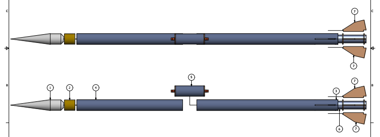
US Patent No. 5212946 [1] proposes a concept for a modular, reusable rocket motor. The invention meets both of these criteria by employing reusable and disposable assembly items. Many of these items, such as washers, O-rings, housings, and exhaust nozzles, appear to be standard components, as there are no specifications listed for them anywhere throughout the patent. However, the combination and assembly of these standardized components appear to be unique to this invention.
Figure 3 shows the total assembly of the rocket motor itself. Notable components include the insulating tube, locking washers, gas sealing rings (o-rings), the nozzle, and forward and aft capsules. These last two components secure the entire assembly into place. The patent also discloses that the inventor has found it beneficial to include coating the threads of the forward and aft capsules with a heat tolerant grease, both to prevent them from seizing during operation and prevent gas from leaking out of the motor anywhere other than the exhaust nozzle.
The patent will be used to help design our internal motor assembly. While our focus is not to make a modular rocket motor, we do desire to create a reusable rocket motor. As is demonstrated by the patent, these two concepts are not mutually exclusive from one another. Since the majority of components are standardized, they can be swapped out upon reassembly – that is, if one desired to use the motor more than once, certain components could easily be swapped during the propellant refilling process.
Article:
Bianchi et. al.’s article [2] focuses on the preservation of the exhaust nozzle for the motor. While the article primarily details large solid rocket motors, the concepts and results discussed can be applied to smaller solid rocket motors as well. While at this point it is uncertain as to whether our nozzle will require coating or not, the knowledge of how to apply coatings will be invaluable going forward.
Ablative materials are the most commonly chosen material for protecting the metallic housing of the nozzle. Not only do they provide protection to the metal, but they also allow and encourage the expansion of combustive gases in solid rocket motors. These coatings will inevitably erode over time, due to the harsh operational conditions they endure. Such erosion results in nominal performance reductions. Ablative materials are divided into two different categories: prolyzing (charring) and non-prolyzing (non-charring). Prolyzing materials are made from a matrix (thermosetting polymer), such as phenolic, and a reinforcing material, such as carbon or silica. The erosion of prolyzing materials is caused by endothermic reactions when exposed to heat. Such reactions release gaseous products, which leaves a porous, charred material as the result of the reaction, which preserves the nozzle contour and integrity. This char is consumed through oxidation by the boundary-layer gases, which results in the nozzle surface receding. This erosion process is heavily investigated through the rest of the article, and is cited as being the most common form of ablative coating on reusable nozzles.
References:
[1] Hans, P.C., Rosenfield, G.C., Meyer, D.H., 1993, “Reloadable/Modular Solid Propellant Rocket Motor.” USA. US005212946.
[2] Bianchi, D., Turchi, A., Nasuti, F., Onofri, M., 2013, “Chemical Erosion of Carbon-Phenolic Rocket Nozzles with Finite-Rate Surface Chemistry,” Journal of Propulsion and Power, Vol. 25 No.5, pp. 1220-1230.
Propellant Manufacture
Patent:
The selected patent compares an innovative approach to making and combining solid rocket fuel to the traditional method. According to the background, traditional solid fuel rocket propellants (including binder, oxidizer, fuel and other additives) were traditionally mixed together and then cured within the rocket. One of the primary issues of the aforementioned method of preparing the solid rocket propellant is that it must be done under a vacuum in order to prevent air from becoming trapped within the mixture; trapped air pockets in the propellant could lead to an explosion or a case burn through. Secondly, the in-situ curing method can lead to tensile and shear forces acting across the bond area as the mixture cools which could potentially lead to bond failure and/or propellant cracking.
The innovative solution proposed in the patent is the development of ‘strips’ of propellant which may be molding by an appropriate method (such as an extruder) to avoid the entrapment of air within the mixture. These strips of propellant combine the fuel, oxidizer, binder, and other additions into thin films which may then be wound together to form solid cylindrical shapes. The most important advantage of using pre-formed strips of solid rocket propellant is that various strips of propellant mixtures may be combined to provide variable thrust as the propellant burns. Additionally, the preformed strips may be inserted into pre-manufactured rocket casings.
Perhaps the most relevant aspect of the patent to the experimental motor design project this semester is the application of variable solid fuels within a single motor to produce customized thrust outputs. Since the thrust delivered by the rocket propellant is affected by both the chemical composition and geometry of the solid fuel.
Article:
When utilizing solid fuel propellant, cracks which are present may result in catastrophic consequences such as motor failure or a case burn-through. When multiple millions of dollars are invested into the rocket payloads it is crucial to ensure that any surface cracks do not unexpectedly cause issues. According to this journal article, finite element analysis should be used to assess whether or not a crack affects the structural reliability of the solid rocket propellant. There are many factors to consider when determining if a crack endangers the rocket but in particular the critical crack size for a centrally perforated grain is examined using linear fracture mechanics.
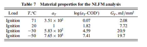
From the experimental results it can be shown that size of the fracture process zone (FPZ) and the crack opening displacement (COD) both increase as temperature decreases. Therefore cracks may become exceptionally problematic since the propellant is increasingly brittle. The results are shown below in Table 7. The fracture energy is shown as G_F.
For our project, it will be important to note that cracks and imperfections in the solid rocket propellant can have significant effects on the effectiveness and the safety of the motor. As such, it will be important to ensure that the experimental motors used for the rocket are manufactured with care.
References:
[1] Preston S. Craig and Gordon S. Oakley, 1988, “Method for Making Solid Rocket Propellant.” United States Patent 4792423.
[2] Giuseppe Tussiwand, Victor Saouma, Rober Terzenbach, and Luigi De Luca, 2009, "Fracture Mechanics of Composite Solid Rocket Propellant Grains: Material Testing " Journal of Propulsion and Power, 25(1), pp. 60-72.