Experimental Laboratories and Research Facilities
My research program examines various aspects of erosion and sedimentation through the use of experimentation, theory, field studies, and numerical modeling. Below is a brief summary of the experimental laboratories and research facilities currently available for research.
Particle Image Velocimetry
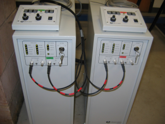
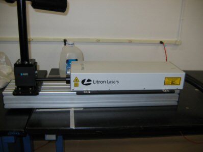
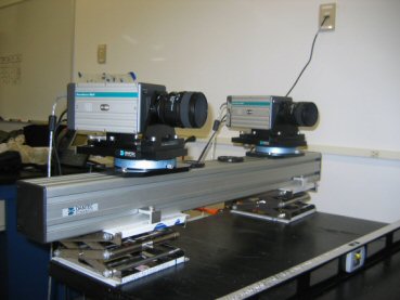
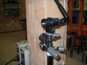
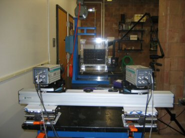
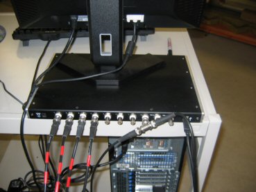
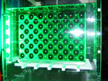
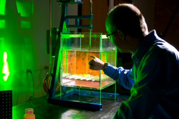
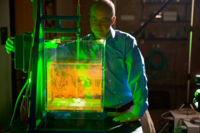
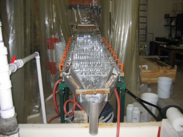
The system is comprised of a dual-cavity 50 mJ Nd-YAG laser wherein each laser can be operated at 100 Hz. Thus, the dual laser can rectify the flow field at 200 Hz and the time interval between pulses can be ms or less. Images are recorded by two (2) 4 Mp cameras with 4 GB each of RAM and with acquisition speeds up to 250 Hz. Each camera, when focused onto the flow-orthogonal laser light sheet from off-axis mounts, can derive an individual vector field at 200 Hz, measuring vertical and horizontal components of velocity. All data acquisition and synchronization is handled by an external timing hub, dedicated computer, and software. By combining these off-axis datasets, and by exploiting the thickness of the laser light sheet (~1 to 2 mm), the cross-stream velocity component can be determined at the same frequency and spatial resolution of the horizontal and vertical components (i.e., all three turbulent components of velocity).
|
|
|
|
|
|
|
|
|
| Representative photographs of the PIV system located in the Wilkeson Hydraulics Laboratory (WHL) showing all major components (starting in upper-left): two laser power supplies, laser, two video cameras mounted to a common bench, light-guiding arm, the cameras focused on a standard mixing box containing the 3D calibration target, the timing box, the 3D calibration target illuminated by the laser, and the laser oriented into the mixing box illuminating the fluorescent (pink) seed particles. The last two photographs were taken by Doug Levere here at UB. | ||
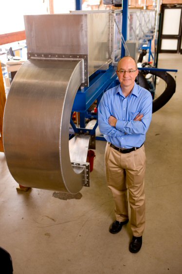
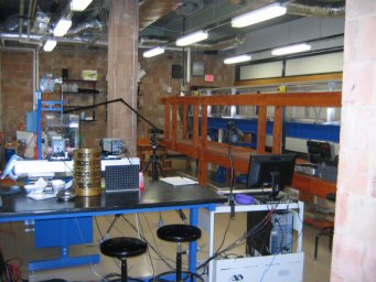
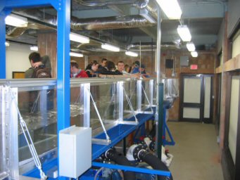
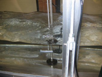
Sediment Recirculating Hydraulic Flume
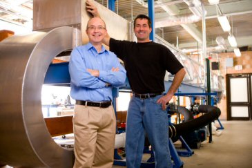
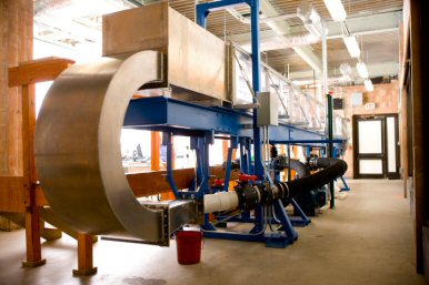
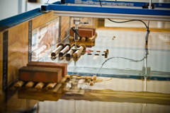
A sediment-recirculating hydraulic channel is located in 155 Wilkeson. The flume is approximately 10-m long, 0.61-m deep, and 0.61-m wide, and was designed by Sean Bennett and built here at UB by Kevin Cullinan and the Department of Physics Machine Shop (Kevin is pictured below with Sean Bennett in the upper left photograph). This facility is driven by two (2) 6-in cast iron, bronze-fitted, closed-coupled, end suction pumps, each with a dedicated 20 HP 3-phase motor and variable speed drive. These pumps can provide up to 1750 GPM each, and they can be operated together or separately. The flume’s slope is controlled by two (2) 2.5-ton machine screw jacks, each with a 1/2- HP motor and 6:1 gear reducer.
 |
 |
 |
 |
 |
|
 |
 |
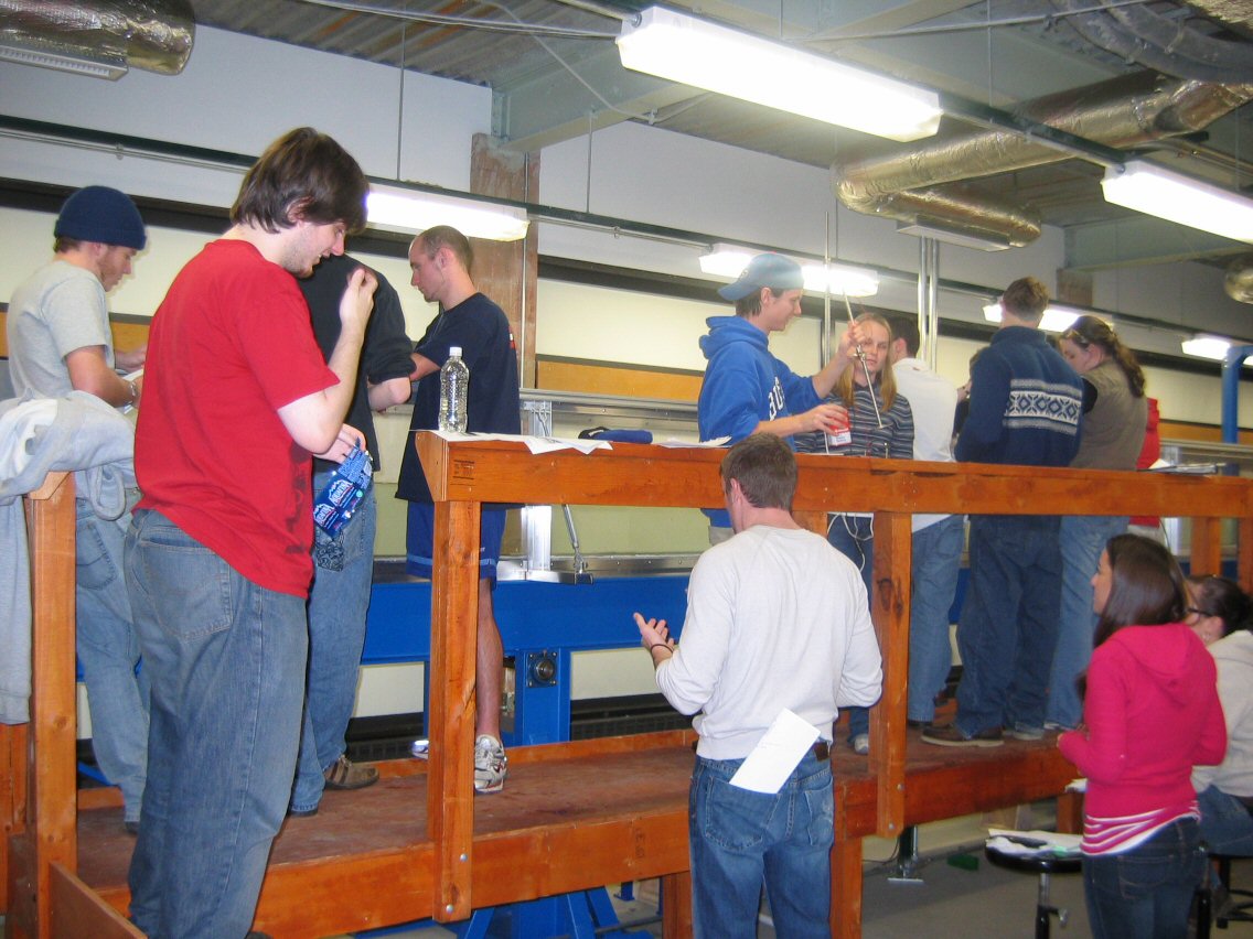 |
| Representative photographs of the sediment-recirculating hydraulic channel located in 155 Wilkeson. The flume was designed by Sean Bennett and built here by Kevin Cullinan and the Department of Physics Machine Shop (Kevin is pictured with Sean Bennett in the upper left photograph). Additional photographs show a 1D electromagnetic current meter, a 3D acoustic Doppler velocimeter, and students taking velocity profiles during GEO350 “Field and Laboratory Techniques.” The upper three photographs were taken by Doug Levere here at UB. | ||
Alluvial Flow Dynamics Facility
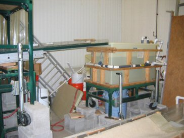
In the Geomorphology Laboratory located in Statler Commissary, a recirculating flume has been constructed to examine flow dynamics in an open channel. The facility is tiltable recirculating (open loop) flume, 1.9 m wide, 7 m long, and 0.5 m deep with fixed banks. Three sump pumps operate in parallel to deliver a maximum discharge of 0.0268 cumecs, monitored using an in-line flow meter. The 6-inch inflow pipe is buried into a 2.0 m wide, 0.9 m deep, and 0.9 m tall headbox filled with cobbles, which dissipates all pump-related turbulence. Fifteen flow straighteners, 0.2 m tall and 0.37 m deep, are installed evenly across the entrance to the flume and downstream of the headbox, whereas 10 adjustable vertical vanes 0.16 m wide and 0.26 m tall are installed at the flume exit to regulate flow depth within the flume. Photogrammetry is used to collect high resolution digital elevation models (DEMs) of the bed surface.
 |
 |
 |
 |
|
|
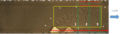
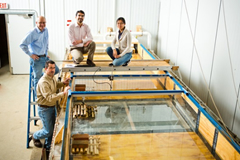
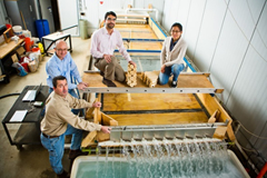
| Representative photographs of the Alluvial Flow Dynamics Facility located in Statler Commissary. These photographs show Sean Bennett and Kevin Cullinan (outside flume), and Mohammad Ghaneeizad and Donghua Cai (atop flume). Additional photographs show an engineered log jam employed in the study and an ELJ attached to the biaxial load cell. These photographs were taken by Doug Levere here at UB. The lower right shows an orthophotograph of the movable-bed experiment displaying the morphodynamic interaction of two ELJs (by Michael Gallisdorfer). | ||
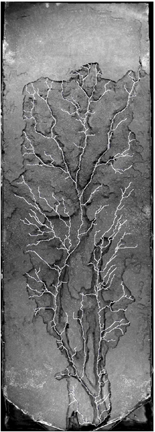
Rainfall Erosion Facility (same flume as above)
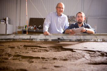
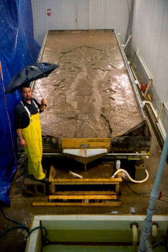
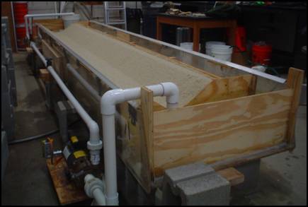
In the Geomorphology Laboratory located in Statler Commissary, a Rainfall Erosion Facility has been constructed to examine free-developed rill network systems using a soil-mantled experimental landscape. The Rainfall Erosion Facility has three components: (1) a 7 × 2.4 m soil box (flume) with adjustable slope and baselevel that was originally housed at the University of Toronto and built by Professor Rorke Bryan; (2) a nozzle-based rainfall simulator capable of delivering rates of 30 to 150 mm/hr at or near terminal velocity; and (3) state-of-the-art digital imaging hardware for producing very high resolution digital elevation models (DEMs) of the evolving bed surface.
 |
 |
 |
 |
||
 |
 |
|
| Representative photographs of the Rainfall Erosion Facility located in Statler Commissary. These photographs show Lee Gordon (sitting next to Sean Bennett and standing in the rain) who spent much time and effort to instrument the facility. Additional photographs show the creation of a rill network system (top and right), the base-station surveying requirements and some targets used in photogrammetry (left), and a pressure-regulated nozzle and the suspended digital camera (lower center). The photographs with Sean Bennett and Lee Gordon were taken by Doug Levere here at UB. | ||
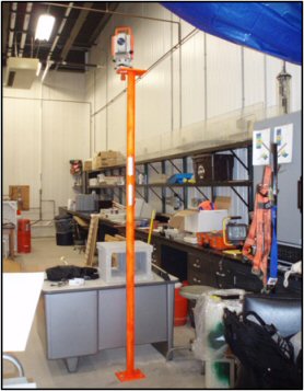
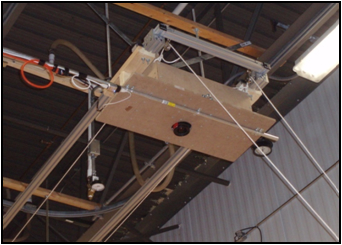
Overland Flow Flume
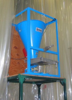
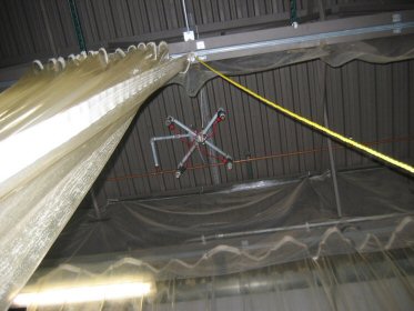
In the Geomorphology Laboratory located in Statler Commissary, a flume was specially designed and built by Distinguished Professor Athol D. Abrahams (emeritus) to study overland flows. The flume is 5.2 m long and 0.4 m wide, with a lower experimental section and an upper entrance channel. Overland flow can be introduced from an upstream head tank and measured with a paddlewheel flow meter. An upstream sediment load also can be supplied by an adjustable sediment feed system suspended above the entrance channel. Mean overland flow velocity can be determined using a salt tracing technique and high-resolution conductivity probe connected to a data acquisition system. Simulated rainfall also can be applied at rates ranging 50 to 150 mm/hr, delivered by pressure-regulated jet nozzles suspended 3.6 m above the flume.
 |
 |
 |
 |
 |
 |
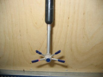
| Representative photographs of the Overland Flow Flume constructed and designed by Distinguished Professor Athol D. Abrahams (emeritus) showing the flume channel with flexible and rigid roughness elements (from Professor G. Li's collaborative research project), upstream sediment feed system, rainfall nozzles, saline tracer apparatus, and upstream water delivery system. | ||
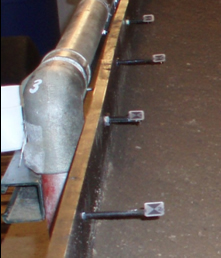
Stream Corridor Physical Model
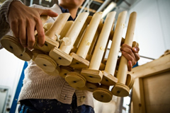
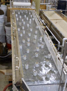
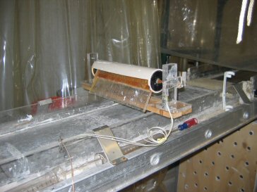
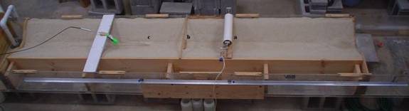
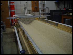
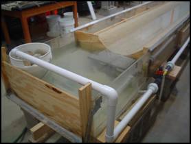
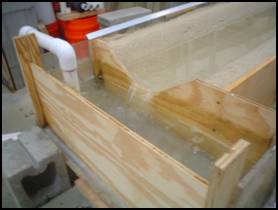
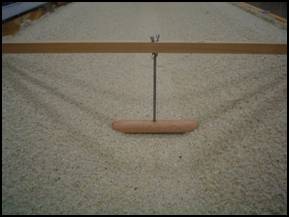
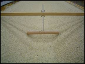
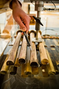
In the Geomorphology Laboratory located in Statler Commissary, a flume was specially designed to conduct distorted Froude-scaled studies of river channels with movable beds and banks. The channel is 3.7 m long not including the head and tail box. The channel is filled with 0.6 to 0.8 mm diameter sand, which is wetted and cut into a trapezoid using an aluminum scraper. Here, the stream corridor channel has a top width of 0.312 m and bottom width of 0.1 m. Water is recirculated by a centrifugal pump, controlled by a gate valve coupled to an inline flow meter. Mean overland flow velocity can be determined using a salt tracing technique and high-resolution conductivity probe connected to a data acquisition system. In this example, the physical model is used to quantify the adjustment of the channel to large woody debris (represented by wooden dowels) placed at discrete locations within the wetted channel.
 |
 |
|
 |
 |
 |
 |
 |
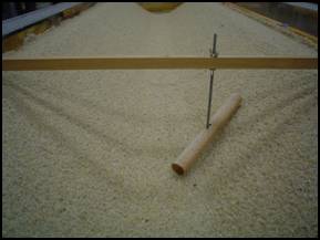 |
Representative photographs of the stream corridor physical model located in Statler Commissary. These photographs show a trapezoidal channel cut into a medium sand with an imposed flow rate that is below the threshold of motion and a bed slope of 0.002. Flow is recirculated and measured using a inline meter, while average flow velocity within the channel can be determined using a salt-tracer technique. In this application, the alluvial adjustment to large woody debris (represented by wooden dowels) is examined.
|
||
 --
--