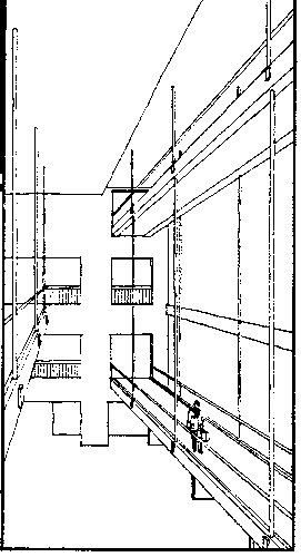
Figure 1: Walkways Before the Collapse (source: Pfrang and Marshall, 1982)
The suspended walkways are shown in Figure 1. The fourth-floor
walkway (top right in Figure 1) collapsed and fell on the second-floor
walkway (bottom right in Figure 1). The third-floor walkway, on the
left in Figure 1, was not involved in the collapse. Each walkway
is about 120 ft long and 18 ft wide.
Figure 1: Walkways Before the Collapse (source: Pfrang and Marshall,
1982)
Each walkway consists of four main parts: two stringers (I-beams running along the length of each walkway), three box beams (running across the width of each walkway), a concrete deck (providing the walkway surface), and six threaded hanger rods (each 1.25 inches in diameter) passing through the box beams. The box beams rested on washers and nuts attached to the hanger rods. The fourth-floor walkway collapsed when the washers and nuts pulled through the box beams. In Figure 2, a stringer is shown in the foreground running left to right, a box beam is in white running perpendicular to the stringer, the deck is shown above the box beam in the cutaway, and a hanging rod is shown in white running up and down.
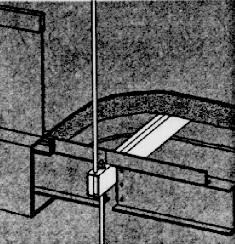
Figure 2: Cutaway of a Walkway (source: Pfrang and Marshall, 1982)
In the original design, the hanger rods were continuous and ran from the ceiling to the bottom of the second-floor box beams. During construction, change orders were suggested and approved to change the hanger rod configuration. Each continuous rod was replaced with two rods - one running from the ceiling to the bottom of the fourth-floor box beams and one running from the top of the fourth-floor box beam to the bottom of the second-floor box beam. The "as-built" hanger rods are shown in Figure 3.
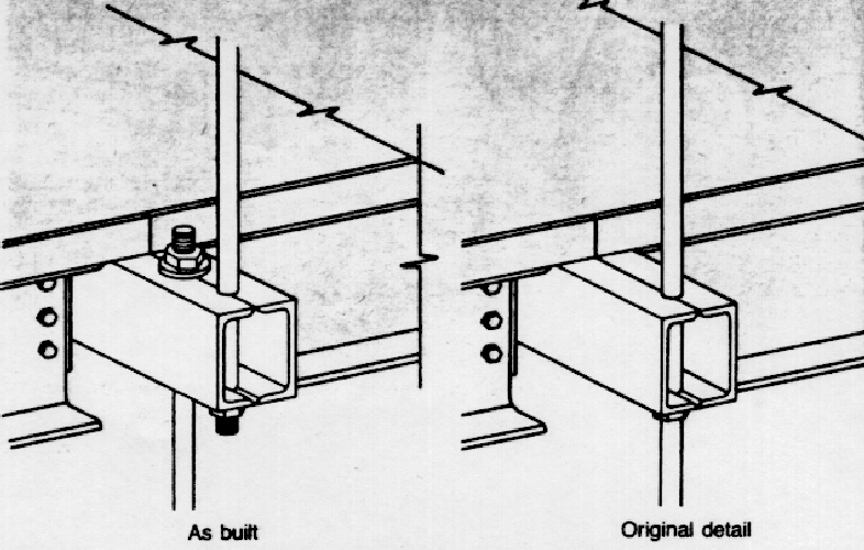
Figure 3: Reconfiguration of Hanger Rods (source: Pfrang and Marshall,
1982)
In the case study, you are charged with investigating the Hyatt Regency disaster. Specifically, your consulting firm has been hired to analyze three aspects of the disaster. First, you must determine whether the capacity of the walkway as designed was greater than the design load. Second, you are to perform experiments to determine whether the change order resulted in an increased load at the point of ultimate failure. Third, you must determine whether the capacity of the walkway was greater than the actual load.
Please summarize your findings in a two-page report. Your report
should follow the following outline:
In addition, 15 points will depend on the quality of your technical writing. For full credit, be sure to avoid spelling and grammatical errors. Use headings to show the structure of your report. Refer to tables and figures in the body of the report. Make sure tables and figures have numbers and titles. Include units on all numbers.
For more information on the ethical aspects of the case, see this
site .
For more photographs, go here and click on "Hyatt Regency Walkway Photographs" or "Miscellaneous Hyatt Regency Walkway Photographs"
For more technical information, see E.O. Pfrang and R. Marshall, "Collapse
of the Kansas City Hyatt Regency Walkways", Civil Engineering, 65-68,
July, 1982.
The live load comes from the people on the walkway. Video taken before the collapse showed about 80 people on the fourth-floor walkway. Use a reasonable value for the average weight of the people.